Apollo: Communications with the Moon
The Apollo program required solving an unprecedented communications challenge: maintaining reliable voice, telemetry, television
The Apollo program landed twelve astronauts on the Moon between 1969 and 1972, but the engineering challenge was not just getting there — it was maintaining continuous two-way communication across a quarter-million miles of vacuum. Every voice transmission, every byte of telemetry, every frame of television, and every tracking measurement had to pass through the Unified S-Band (USB) system, a single-carrier architecture that handled all communications and tracking functions on one frequency band.
The Unified S-Band System
Before Apollo, Mercury and Gemini used separate VHF, UHF, and C-band systems for voice, telemetry, and tracking — each requiring its own transmitter, receiver, and antenna. This approach was weight-prohibitive for a lunar mission. In December 1962, NASA's Office of Tracking and Data Acquisition proposed a unified approach: a single S-band carrier that would carry all uplink and downlink information, eliminating the need for multiple radio systems and their backups.
The S-band frequency range (2-4 GHz) was chosen as a compromise among equipment availability (inherited from JPL's Deep Space Instrumentation Facility), frequency allocations, circuit losses, and antenna gains. A propagation window with low galactic noise levels was selected around 2.2 GHz. The system used coherent two-way Doppler tracking and pseudo-random noise (PRN) ranging — techniques developed by JPL for unmanned planetary missions — adapted for the unique requirements of crewed lunar flight.
Uplink Architecture (Ground to Spacecraft)
The ground-to-spacecraft uplink consisted of a single S-band carrier at 2106.4 MHz, phase-modulated by two subcarriers and a PRN ranging code. Narrowband phase modulation (PM) was used to ensure a phase-stable carrier component was transmitted to the spacecraft for coherent transponding.
- Voice Subcarrier (30 kHz): Frequency modulated with a peak deviation of 7.5 kHz, carrying ground-to-astronaut voice communications
- Up-Data Subcarrier (70 kHz): Frequency modulated with a peak deviation of 5 kHz, carrying digital commands via phase-shift keying (PSK) at 1 kbit/s
- PRN Ranging Code: A 5,456,682-bit binary sequence transmitted at 1 megabit rate, appearing as a symmetrical (sin²x)/x² power spectrum centered on the carrier
The composite uplink signal was generated at one of three MSFN primary stations — Goldstone (California), Madrid (Spain), or Canberra (Australia) — each equipped with an 85-foot Cassegrain-feed antenna. A smaller 30-foot acquisition antenna with wider beamwidth was used for initial signal acquisition before handing off to the main antenna.
Downlink Architecture (Spacecraft to Ground)
The Command and Service Module (CSM) transmitted two simultaneous S-band carriers:
- PM Carrier (2287.5 MHz): Coherently related to the uplink carrier by the frequency ratio 240/221. Carried voice, PCM telemetry, biomedical data, ranging code, and emergency key via phase modulation of two subcarriers (1.024 MHz and 1.25 MHz)
- FM Carrier (2272.5 MHz): Independent carrier, frequency-modulated to carry wideband television and high-rate data dump. Separated 15 MHz from the PM carrier
The Lunar Module (LM) transmitted only a single downlink carrier at 2282.5 MHz. During normal operations, this was coherently related to the uplink. When television was transmitted, the LM switched to FM modulation, carrying TV along with PCM telemetry and voice subcarriers on the same carrier.
Spacecraft Transponder
The heart of the spacecraft communications was the Unified S-Band transponder — a dual-conversion superheterodyne receiver/exciter combination. The receiver operated at a center frequency of 2106.4 MHz with a noise figure below 11 dB. A narrowband phase-lock tracking loop (approximately 1 kHz bandwidth) reconstructed the carrier component of the incoming PM signal and provided the frequency and phase reference for the coherent downlink transmitter.
The transponder contained two transmitter exciters: a PM exciter for normal voice and telemetry, and a separate FM exciter for television. The CSM transponder could operate both simultaneously, while the LM transponder contained only the PM exciter. A premodulation processor accepted signals from voice, PCM telemetry, biomedical sensors, and television equipment, routing them to the appropriate subcarrier oscillators and mixing networks before feeding the composite signal to the transponder modulator.
Power Amplifiers
The CSM power amplifier assembly contained two 20-watt traveling-wave tube (TWT) amplifiers with switching circuitry. During normal PM-only operation, one amplifier provided 11.2 watts at the antenna terminals (after losses through the multiplexer and switches). When simultaneous PM and FM transmission was required — such as during television broadcasts — the second amplifier was activated for the FM link, delivering 12.6 watts. If both TWTs failed, a 0.125-watt backup signal derived from the PM exciter was available for emergency communications.
The LM used a different amplifier design: two selectable amplitrons providing 18.6 watts (primary) or 14.8 watts (secondary) at the diplexer output. The LM also had a separate 0.75-watt low-power mode for proximity operations near the CSM.
Antenna Systems
The CSM carried five antennas for S-band communications:
- Four Low-Gain Antennas: Cavity-backed helices spaced at 90° intervals around the spacecraft periphery, providing near-omnidirectional coverage. Only one element was active at a time, providing approximately 20 dBi gain over 80% of the sphere
- High-Gain Antenna Array: An 11-inch diagonal wide-beam horn flanked by four 31-inch diameter parabolic reflectors. Three selectable beamwidths — 40°, 11.3°, and 4.4° — provided gains of approximately 14, 22, and 28 dBi respectively. The antenna used electronic conical scan tracking, where angle-error information was encoded as amplitude modulation on the received signal
The LM carried two S-band antennas: a steerable 26-inch parabolic dish (20.5 dBi gain) used during orbit, descent, and ascent, and a manually erected 34 dBi antenna for high-bandwidth communication during lunar surface EVA operations. The steerable antenna provided 174° azimuth and 330° elevation coverage, with automatic tracking once the signal was within the 25° RF capture cone.
Ground Network (MSFN)
The Manned Space Flight Network consisted of two types of stations:
- 85-foot stations (3): Located at Goldstone, Madrid, and Canberra — spaced approximately equidistant around the globe to provide continuous coverage at altitudes above 10,000 nautical miles. These were the primary deep-space tracking stations, each equipped with an 85-foot (26-meter) Cassegrain antenna for S-band uplink/downlink
- 30-foot stations (multiple): Positioned between the 85-foot stations at Bermuda, Corpus Christi, Hawaii, and other sites to provide coverage during launch, earth orbit, and near-earth coast phases
Each 85-foot station used a diplexer providing approximately 190 dB of isolation between transmit and receive frequencies (separated by about 180 MHz after accounting for the 240/221 transponder ratio and two-way Doppler). The main receiver threshold was approximately -157 dBm for the narrowband PM channel. A microwave data link connected the distant antenna site to the control building, transmitting six RF channels carrying all downlink and uplink baseband signals.
Tracking and Ranging
Apollo used two primary tracking methods simultaneously:
Coherent Doppler:The spacecraft transponder locked to the uplink carrier and retransmitted it coherently at the 240/221 frequency ratio. By measuring the Doppler shift of the returned carrier against the known uplink frequency, ground stations could determine the spacecraft's radial velocity with extreme precision. This was possible because the phase-lock loop in the transponder maintained a stable phase relationship between received and transmitted carriers.
PRN Ranging: A pseudo-random noise code — a 5,456,682-bit binary sequence generated at 1 megabit rate — was phase-modulated onto the uplink carrier. The spacecraft transponder detected this code and retransmitted it on the downlink carrier. Ground stations measured the round-trip propagation time by counting reference oscillator cycles between transmission and reception of the code, correcting for spacecraft motion during the delay. At lunar distance, this delay was approximately 2.56 seconds (round trip), giving a range resolution of better than one meter.
Modulation and Signal Design
The USB system used a carefully designed modulation hierarchy to multiplex multiple information streams onto a single carrier:
- Narrowband PM (uplink and PM downlink): Voice (30 kHz subcarrier, FM) and data (70 kHz subcarrier, PSK) were frequency-modulated onto subcarriers, then phase-modulated onto the S-band carrier. This preserved a coherent carrier component for tracking
- Wideband FM (television): Video was frequency-modulated directly onto a separate carrier at 2272.5 MHz (CSM) or onto the main carrier (LM), providing the wider bandwidth needed for television
- PCM Telemetry: Binary pulse-code-modulated data at either 51.2 kbit/s (high rate) or 1.6 kbit/s (low rate) modulated the 1.024 MHz telemetry subcarrier via PSK
- Emergency Key: A 512 kHz subcarrier provided a backup Morse-code capability, translated to a 1 kHz on-off tone at the ground receiver
The two downlink subcarrier frequencies (1.024 MHz and 1.25 MHz) were deliberately placed near the first null of the turnaround ranging code spectrum to minimize interference between telemetry and ranging signals.
Television Broadcasting
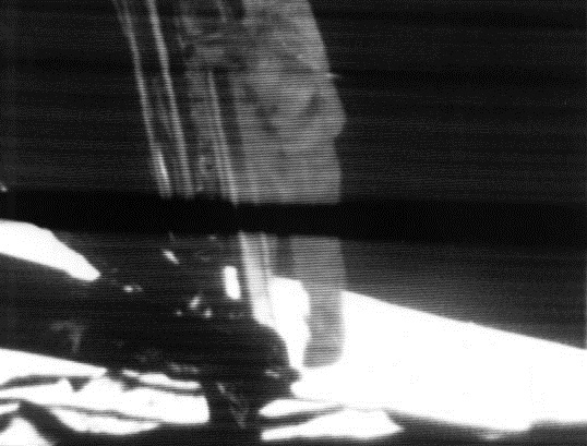
Apollo 11's television broadcast on July 20, 1969 was one of the most-watched events in history. The slow-scan TV camera produced 320-line black-and-white images at 10 frames per second, which were converted to standard 525-line NTSC at 30 fps using an scan converter at Honeysuckle Creek tracking station before being relayed to Houston. The TV signal required the full 5.3 MHz bandwidth of the FM downlink, which meant the PCM telemetry and voice subcarriers shared the FM carrier during television transmissions. At lunar distance, the signal received by the 85-foot MSFN antennas had a carrier-to-noise density ratio (C/N₀) of approximately 68 dB-Hz — sufficient for usable television but requiring the full gain of the high-gain antenna array on the spacecraft.
Signal Propagation
At the Moon's average distance of 384,400 km, radio signals traveled in 1.28 seconds one way. This light-time delay meant that conversations between Mission Control and lunar surface astronauts had a minimum 2.56-second round-trip delay. During Apollo 11's first EVA, this delay was clearly audible in the exchanges between Armstrong, Aldrin, and CAPCOM Bruce McCandless in Houston. The free-space path loss at 2.2 GHz over lunar distance was approximately 234 dB, meaning the 20-watt spacecraft transmitter delivered roughly 10⁻²¹ watts to the ground antenna — billions of times weaker than the background noise before processing gain was applied.
Lunar Surface Communications
During EVA operations on the lunar surface, the LM's steerable S-band antenna served as the primary link to Earth. The erectable high-gain antenna (34 dBi) was deployed by the astronauts to provide the higher data rates needed for television. Voice communication between astronauts on the surface used VHF radios operating at 296.8 MHz (Channel A) and 259.7 MHz (Channel B), with 3.8 watts RF output. Channel B also carried PCM telemetry from the Portable Life Support System (PLSS) and received VHF ranging data from the CSM for relay to Earth. During periods when the MSFN and CSM were not in line of sight, the LM communicated directly with Earth via S-band.
Legacy
The Unified S-Band system designed for Apollo became the template for all subsequent deep-space communications. The PRN ranging technique, coherent Doppler tracking, subcarrier multiplexing, and the frequency plan itself were adopted — with upgrades — for the Voyager, Galileo, Cassini, and Mars exploration missions. The 70-meter Deep Space Network antennas built for Apollo remain the backbone of NASA's deep-space communications infrastructure today, still operating at S-band and X-band frequencies that trace their lineage directly to the system that connected humanity to its first steps on another world.
Illustrations


Timeline
Sources & Further Reading
- NASA TN D-6902 - Apollo Experience Report: S-Band System Signal Design and Analysis
- NASA TN D-2208 - Unified S-Band Telecommunication Techniques for Apollo Vol. I
- NASA TN D-3350 - Apollo Experience Report: CSM Communications Subsystem
- NASA TN D-5869 - Apollo Experience Report: LM Communications System
- Bellcomm TM-71-2034-3 - Predictions of Apollo USB Communications Performance